LWPM Comfort Module/PCB: Różnice pomiędzy wersjami
Przejdź do nawigacji
Przejdź do wyszukiwania
| (Nie pokazano 29 pośrednich wersji utworzonych przez tego samego użytkownika) | |||
| Linia 6: | Linia 6: | ||
PCB mogą się nieznacznie różnić od rzeczywistych (np kolorem lub jakością wykonania) | PCB mogą się nieznacznie różnić od rzeczywistych (np kolorem lub jakością wykonania) | ||
| + | |||
| + | == Moduł w wersji bez obudowy == | ||
{| class="wikitable" | {| class="wikitable" | ||
|- | |- | ||
| + | ! nazwa i wersja | ||
! góra PCB | ! góra PCB | ||
! spód PCB | ! spód PCB | ||
! opis | ! opis | ||
| − | |||
|- | |- | ||
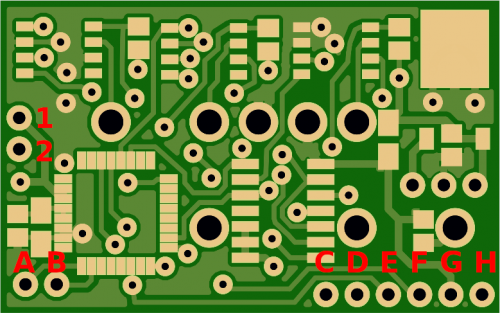
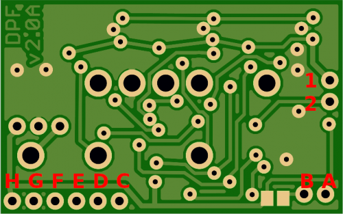
| + | | '''DPF Monitor v2.0''' | ||
| + | 2017-10-31 | ||
| + | |||
| + | [https://files.lwpm.eu/LWPMComfortModule/hardware/old/DPFMonitor-AstraH_v1.1_2017-10-31.sch schemat] | ||
| + | [https://files.lwpm.eu/LWPMComfortModule/hardware/old/DPFMonitor-AstraH_v1.1_2017-10-31.brd PCB] | ||
| [[Plik:PCB-top-2017-10-31.png|500px]] | | [[Plik:PCB-top-2017-10-31.png|500px]] | ||
| [[Plik:PCB-bottom-2017-10-31.png|500px]] | | [[Plik:PCB-bottom-2017-10-31.png|500px]] | ||
| Linia 27: | Linia 34: | ||
* G - GND | * G - GND | ||
* H - +5V | * H - +5V | ||
| − | |||
| − | |||
|- | |- | ||
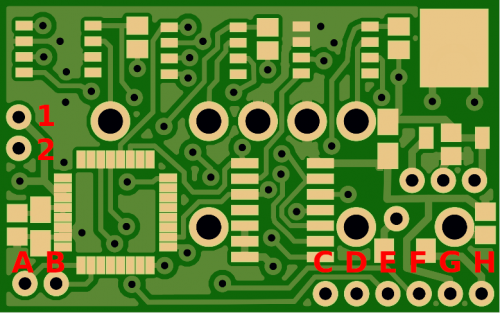
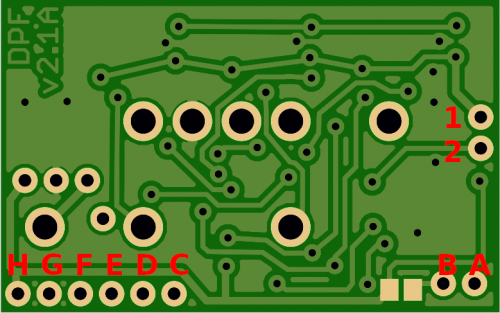
| + | | '''DPF Monitor v2.1''' | ||
| + | 2017-12-29 | ||
| + | |||
| + | [https://files.lwpm.eu/LWPMComfortModule/hardware/old/DPFMonitor-AstraH_v1.1_2017-12-29.sch schemat] | ||
| + | [https://files.lwpm.eu/LWPMComfortModule/hardware/old/DPFMonitor-AstraH_v1.1_2017-12-29.brd PCB] | ||
| + | | [[Plik:PCB-top-2017-12-29.png|500px]] | ||
| + | | [[Plik:PCB-bottom-2017-12-29.png|500px]] | ||
| | | | ||
| + | * 1 - +5V | ||
| + | * 2 - LED- | ||
| + | * A - C2D | ||
| + | * B - C2CK | ||
| + | * C - nie używane | ||
| + | * D - nie używane | ||
| + | * E - UART_TX | ||
| + | * F - UART_RX | ||
| + | * G - GND | ||
| + | * H - +5V | ||
| + | |- | ||
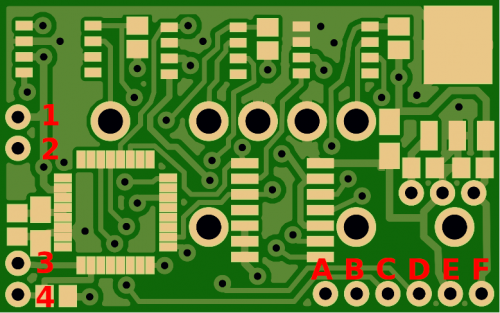
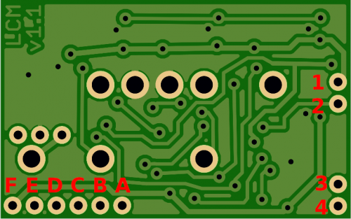
| + | | '''LWPM Comfort Module v1.1''' | ||
| + | 2018-02-23 | ||
| + | |||
| + | [https://files.lwpm.eu/LWPMComfortModule/hardware/old/LWPMComfortModuleAstra-v1.1_2018-02-23.sch schemat] | ||
| + | [https://files.lwpm.eu/LWPMComfortModule/hardware/old/LWPMComfortModuleAstra-v1.1_2018-02-23.brd PCB] | ||
| + | | [[Plik:PCB-top-2018-02-23.png|500px]] | ||
| + | | [[Plik:PCB-bottom-2018-02-23.png|500px]] | ||
| | | | ||
| − | + | * 1 - +5V | |
| − | + | * 2 - LED- | |
| + | * 3 - C2D | ||
| + | * 4 - C2CK | ||
| + | * A - nie używane | ||
| + | * B - nie używane | ||
| + | * C - UART_TX | ||
| + | * D - UART_RX | ||
| + | * E - GND | ||
| + | * F - +5V | ||
|- | |- | ||
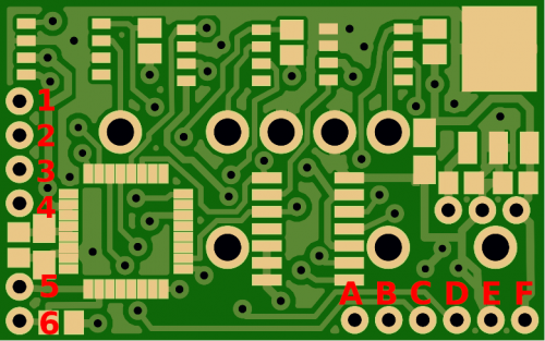
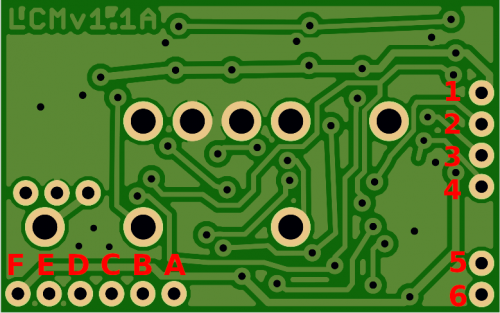
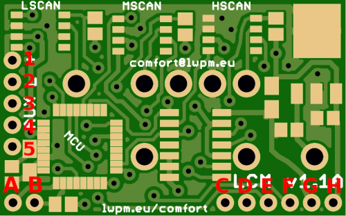
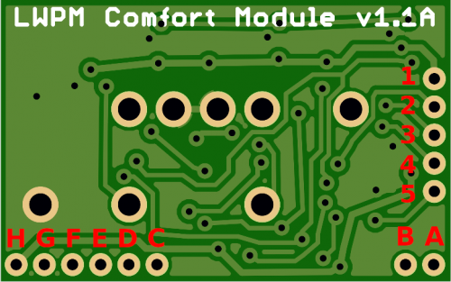
| + | | '''LWPM Comfort Module v1.1A''' | ||
| + | 2018-06-13 | ||
| + | |||
| + | [https://files.lwpm.eu/LWPMComfortModule/hardware/old/LWPMComfortModuleAstra_v1.1A_2018-06-13.sch schemat] | ||
| + | [https://files.lwpm.eu/LWPMComfortModule/hardware/old/LWPMComfortModuleAstra_v1.1A_2018-06-13.brd PCB] | ||
| + | | [[Plik:PCB-top-2018-06-13.png|500px]] | ||
| + | | [[Plik:PCB-bottom-2018-06-13.png|500px]] | ||
| | | | ||
| − | + | * 1 - +5V | |
| − | + | * 2 - LED- | |
| − | + | * 3 - AUX2 | |
| + | * 4 - AUX1 | ||
| + | * 5 - C2D | ||
| + | * 6 - C2CK | ||
| + | * A - nie używane | ||
| + | * B - nie używane | ||
| + | * C - UART_TX | ||
| + | * D - UART_RX | ||
| + | * E - GND | ||
| + | * F - +5V | ||
|- | |- | ||
| + | | '''LWPM Comfort Module v1.1A''' | ||
| + | 2018-09-18 | ||
| + | |||
| + | [https://files.lwpm.eu/LWPMComfortModule/hardware/old/LWPMComfortModuleAstra-v1.1A_2018-09-18.sch schemat] | ||
| + | [https://files.lwpm.eu/LWPMComfortModule/hardware/old/LWPMComfortModuleAstra-v1.1A_2018-09-18.brd PCB] | ||
| + | | [[Plik:PCB-top-2018-09-18.png|500px]] | ||
| + | | [[Plik:PCB-bottom-2018-09-18.png|500px]] | ||
| | | | ||
| − | + | * 1 - +5V | |
| − | + | * 2 - LED- | |
| − | + | * 3 - AUX1 | |
| + | * 4 - AUX2 | ||
| + | * 5 - AUX3 | ||
| + | * A - C2D | ||
| + | * B - C2CK | ||
| + | * C - nie używane | ||
| + | * D - nie używane | ||
| + | * E - UART_TX | ||
| + | * F - UART_RX | ||
| + | * G - GND | ||
| + | * H - +5V | ||
|- | |- | ||
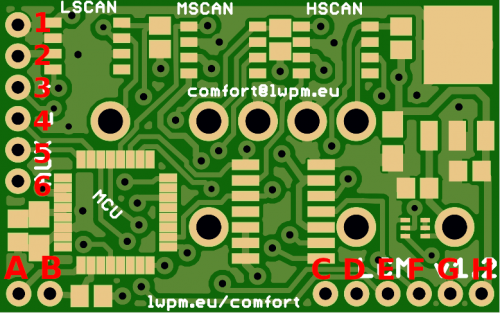
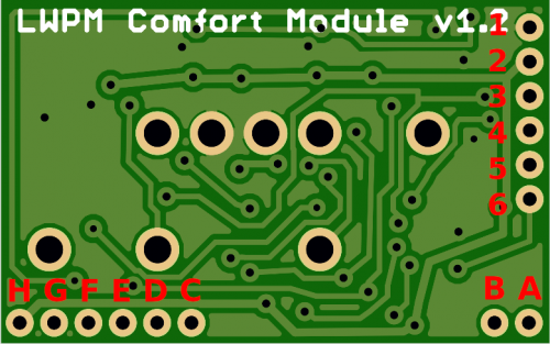
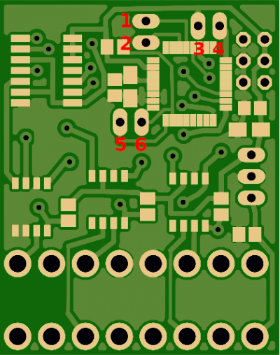
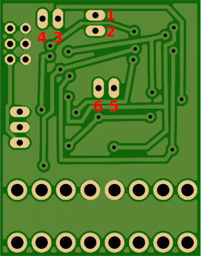
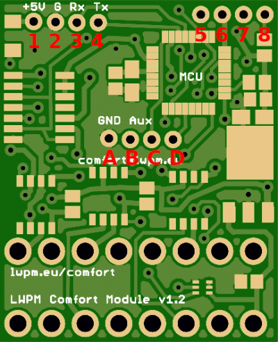
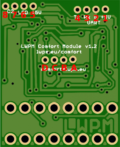
| + | | '''LWPM Comfort Module v1.2''' | ||
| + | 2019-05-30 | ||
| + | |||
| + | [https://files.lwpm.eu/LWPMComfortModule/hardware/old/LWPMComfortModuleAstra-v1.2_2019-05-30.sch schemat] | ||
| + | [https://files.lwpm.eu/LWPMComfortModule/hardware/old/LWPMComfortModuleAstra-v1.2_2019-05-30.brd PCB] | ||
| + | | [[Plik:PCB-top-2019-05-30.png|500px]] | ||
| + | | [[Plik:PCB-bottom-2019-05-30.png|500px]] | ||
| | | | ||
| − | + | * 1 - GND | |
| − | + | * 2 - +5V | |
| − | + | * 3 - LED- | |
| + | * 4 - AUX1 | ||
| + | * 5 - AUX2 | ||
| + | * 6 - AUX3 | ||
| + | * A - C2D | ||
| + | * B - C2CK | ||
| + | * C - nie używane | ||
| + | * D - nie używane | ||
| + | * E - UART_TX | ||
| + | * F - UART_RX | ||
| + | * G - GND | ||
| + | * H - +5V | ||
|- | |- | ||
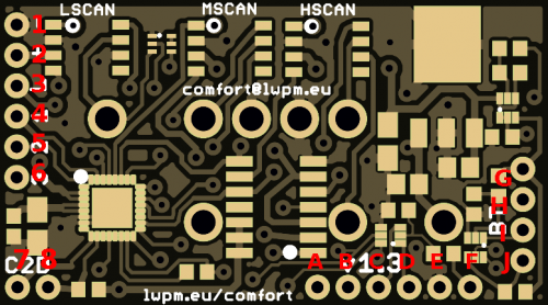
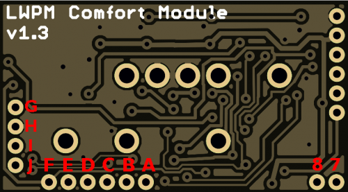
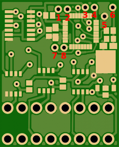
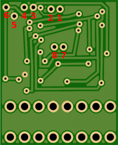
| + | | '''LWPM Comfort Module v1.3''' | ||
| + | 2021-05-07 | ||
| + | |||
| + | [https://files.lwpm.eu/LWPMComfortModule/hardware/old/LWPMComfortModuleAstra-v1.3_QFN32_2021-05-07.sch schemat] | ||
| + | [https://files.lwpm.eu/LWPMComfortModule/hardware/old/LWPMComfortModuleAstra-v1.3_QFN32_2021-05-07.brd PCB] | ||
| + | | [[Plik:LCM_PCB_v13_top_QFN32.png|500px]] | ||
| + | | [[Plik:LCM_PCB_v13_bottom_QFN32.png|500px]] | ||
| | | | ||
| − | + | * 1 - GND | |
| − | + | * 2 - +5V | |
| − | + | * 3 - LED- | |
| + | * 4 - AUX1 | ||
| + | * 5 - AUX2 | ||
| + | * 6 - AUX3 | ||
| + | * 7 - C2D | ||
| + | * 8 - C2CK | ||
| + | * A - nie używane | ||
| + | * B - nie używane | ||
| + | * C - UART_RX | ||
| + | * D - UART_TX | ||
| + | * E - GND | ||
| + | * F - +5V | ||
| + | * G - BT_+5V | ||
| + | * H - GND | ||
| + | * I - BT_TX | ||
| + | * J - BT_RX | ||
|- | |- | ||
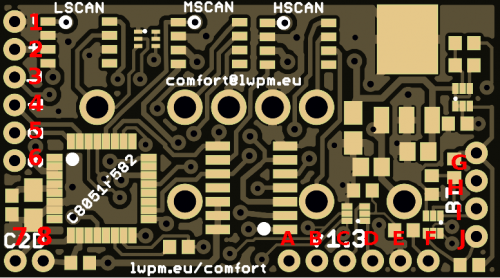
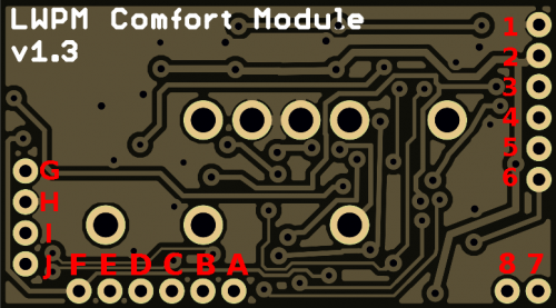
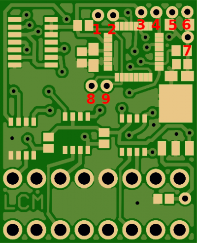
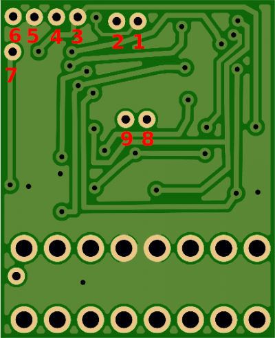
| − | | [[ | + | | '''LWPM Comfort Module v1.3''' |
| − | | [[Plik: | + | 2021-05-07 |
| + | |||
| + | [https://files.lwpm.eu/LWPMComfortModule/hardware/old/LWPMComfortModuleAstra-v1.3_QFP32_2021-05-07.sch schemat] | ||
| + | [https://files.lwpm.eu/LWPMComfortModule/hardware/old/LWPMComfortModuleAstra-v1.3_QFP32_2021-05-07.brd PCB] | ||
| + | | [[Plik:LCM_PCB_v13_top_QFP32.png|500px]] | ||
| + | | [[Plik:LCM_PCB_v13_bottom_QFP32.png|500px]] | ||
| | | | ||
* 1 - GND | * 1 - GND | ||
| Linia 64: | Linia 180: | ||
* 5 - AUX2 | * 5 - AUX2 | ||
* 6 - AUX3 | * 6 - AUX3 | ||
| − | * A - | + | * 7 - C2D |
| − | * B - | + | * 8 - C2CK |
| + | * A - nie używane | ||
| + | * B - nie używane | ||
* C - UART_RX | * C - UART_RX | ||
* D - UART_TX | * D - UART_TX | ||
| − | * E - | + | * E - GND |
| − | * F - | + | * F - +5V |
| − | * G - C2CK | + | * G - BT_+5V |
| − | * | + | * H - GND |
| − | | [https://files.lwpm.eu/LWPMComfortModule/hardware/ | + | * I - BT_TX |
| − | [https://files.lwpm.eu/LWPMComfortModule/hardware/ | + | * J - BT_RX |
| + | |} | ||
| + | |||
| + | == Moduł w wersji w obudowie == | ||
| + | |||
| + | {| class="wikitable" | ||
| + | |- | ||
| + | ! nazwa i wersja | ||
| + | ! góra PCB | ||
| + | ! spód PCB | ||
| + | ! opis | ||
| + | |- | ||
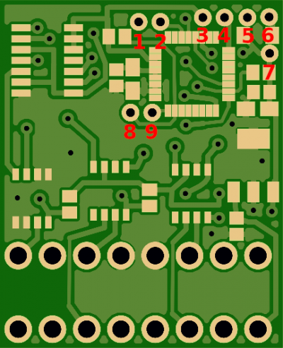
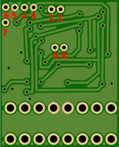
| + | | '''DPF Monitor v1.0''' | ||
| + | 2017-07-21 | ||
| + | |||
| + | [https://files.lwpm.eu/LWPMComfortModule/hardware/old/DPFMonitor_v1.0_2017-07-21.sch schemat] | ||
| + | [https://files.lwpm.eu/LWPMComfortModule/hardware/old/DPFMonitor_v1.0_2017-07-21.brd PCB] | ||
| + | | [[Plik:PCB-ZB-top-2017-07-21.png|400px]] | ||
| + | | [[Plik:PCB-ZB-bottom-2017-07-21.png|400px]] | ||
| + | | | ||
| + | * 1 - UART_RX | ||
| + | * 2 - UART_TX | ||
| + | * 3 - +5V | ||
| + | * 4 - LED- | ||
| + | * 5 - C2D | ||
| + | * 6 - C2CK | ||
| + | |- | ||
| + | | '''DPF Monitor v1.1''' | ||
| + | 2017-10-31 | ||
| + | |||
| + | [https://files.lwpm.eu/LWPMComfortModule/hardware/old/DPFMonitor-ZafiraB_v1.1_2017-10-31.sch schemat] | ||
| + | [https://files.lwpm.eu/LWPMComfortModule/hardware/old/DPFMonitor-ZafiraB_v1.1_2017-10-31.brd PCB] | ||
| + | | [[Plik:PCB-ZB-top-2017-10-31.png|400px]] | ||
| + | | [[Plik:PCB-ZB-bottom-2017-10-31.png|400px]] | ||
| + | | | ||
| + | * 1 - UART_RX | ||
| + | * 2 - UART_TX | ||
| + | * 3 - +5V | ||
| + | * 4 - LED- | ||
| + | * 5 - GND | ||
| + | * 6 - +5V | ||
| + | * 7 - C2CK | ||
| + | * 8 - C2D | ||
| + | |- | ||
| + | | '''DPF Monitor v1.2''' | ||
| + | 2017-12-29 | ||
| + | |||
| + | [https://files.lwpm.eu/LWPMComfortModule/hardware/old/DPFMonitor-ZafiraB_v1.1_2017-12-29.sch schemat] | ||
| + | [https://files.lwpm.eu/LWPMComfortModule/hardware/old/DPFMonitor-ZafiraB_v1.1_2017-12-29.brd PCB] | ||
| + | | [[Plik:PCB-ZB-top-2017-12-29.png|400px]] | ||
| + | | [[Plik:PCB-ZB-bottom-2017-12-29.png|400px]] | ||
| + | | | ||
| + | * 1 - UART_RX | ||
| + | * 2 - UART_TX | ||
| + | * 3 - +5V | ||
| + | * 4 - LED- | ||
| + | * 5 - GND | ||
| + | * 6 - +5V (USB) | ||
| + | * 7 - +5V | ||
| + | * 8 - C2CK | ||
| + | * 9 - C2D | ||
| + | |- | ||
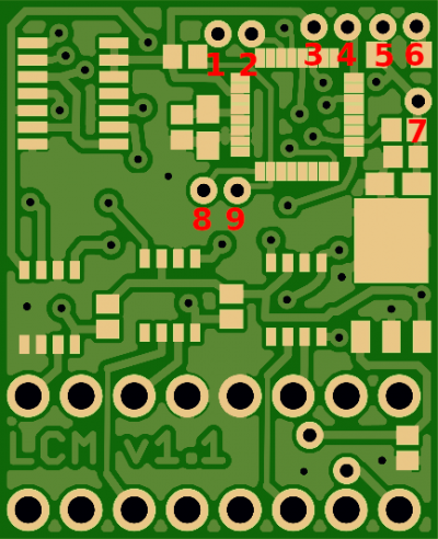
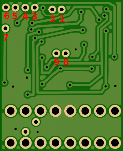
| + | | '''LWPM Comfort Module v1.1''' | ||
| + | 2018-02-23 | ||
| + | |||
| + | [https://files.lwpm.eu/LWPMComfortModule/hardware/old/LWPMComfortModuleZafira-v1.1_2018-02-23.sch schemat] | ||
| + | [https://files.lwpm.eu/LWPMComfortModule/hardware/old/LWPMComfortModuleZafira-v1.1_2018-02-23.brd PCB] | ||
| + | | [[Plik:PCB-ZB-top-2018-02-23.png|400px]] | ||
| + | | [[Plik:PCB-ZB-bottom-2018-02-23.png|400px]] | ||
| + | | | ||
| + | * 1 - UART_RX | ||
| + | * 2 - UART_TX | ||
| + | * 3 - +5V | ||
| + | * 4 - LED- | ||
| + | * 5 - GND | ||
| + | * 6 - +5V (USB) | ||
| + | * 7 - +5V | ||
| + | * 8 - C2D | ||
| + | * 9 - C2CK | ||
| + | |- | ||
| + | | '''LWPM Comfort Module v1.1''' | ||
| + | 2018-06-13 | ||
| + | |||
| + | [https://files.lwpm.eu/LWPMComfortModule/hardware/old/LWPMComfortModuleZafira_v1.1_2018-06-13.sch schemat] | ||
| + | [https://files.lwpm.eu/LWPMComfortModule/hardware/old/LWPMComfortModuleZafira_v1.1_2018-06-13.brd PCB] | ||
| + | | [[Plik:PCB-ZB-top-2018-06-13.png|400px]] | ||
| + | | [[Plik:PCB-ZB-bottom-2018-06-13.png|400px]] | ||
| + | | | ||
| + | * 1 - UART_RX | ||
| + | * 2 - UART_TX | ||
| + | * 3 - +5V | ||
| + | * 4 - LED- | ||
| + | * 5 - GND | ||
| + | * 6 - +5V (USB) | ||
| + | * 7 - +5V | ||
| + | * 8 - C2D | ||
| + | * 9 - C2CK | ||
| + | |- | ||
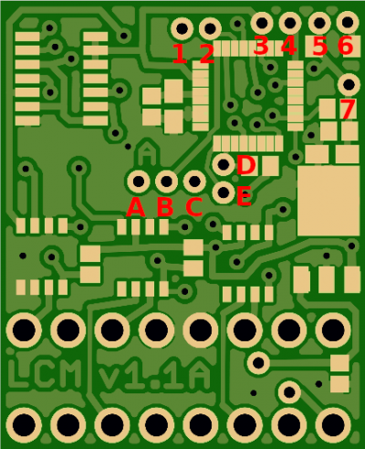
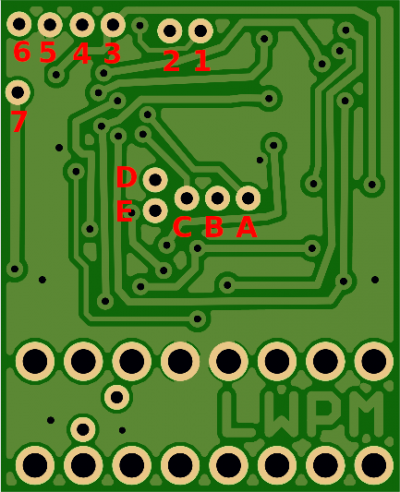
| + | | '''LWPM Comfort Module v1.1A''' | ||
| + | 2019-01-09 | ||
| + | |||
| + | [https://files.lwpm.eu/LWPMComfortModule/hardware/old/LWPMComfortModuleZafira-v1.1A_2019-01-09.sch schemat] | ||
| + | [https://files.lwpm.eu/LWPMComfortModule/hardware/old/LWPMComfortModuleZafira-v1.1A_2019-01-09.brd PCB] | ||
| + | | [[Plik:PCB-ZB-top-2019-01-09.png|400px]] | ||
| + | | [[Plik:PCB-ZB-bottom-2019-01-09.png|400px]] | ||
| + | | | ||
| + | * 1 - UART_RX | ||
| + | * 2 - UART_TX | ||
| + | * 3 - +5V | ||
| + | * 4 - LED- | ||
| + | * 5 - GND | ||
| + | * 6 - +5V (USB) | ||
| + | * 7 - +5V | ||
| + | * A - AUX1 | ||
| + | * B - AUX2 | ||
| + | * C - AUX3 | ||
| + | * D - C2CK | ||
| + | * E - C2D | ||
| + | |- | ||
| + | | '''LWPM Comfort Module v1.2''' | ||
| + | 2019-05-30 | ||
| + | |||
| + | [https://files.lwpm.eu/LWPMComfortModule/hardware/old/LWPMComfortModuleZafira-v1.2_2019-05-30.sch schemat] | ||
| + | [https://files.lwpm.eu/LWPMComfortModule/hardware/old/LWPMComfortModuleZafira-v1.2_2019-05-30.brd PCB] | ||
| + | | [[Plik:PCB-ZB-top-2019-05-30.png|400px]] | ||
| + | | [[Plik:PCB-ZB-bottom-2019-05-30.png|400px]] | ||
| + | | | ||
| + | * 1 - +5V (USB) | ||
| + | * 2 - GND | ||
| + | * 3 - UART_RX | ||
| + | * 4 - UART_TX | ||
| + | * 5 - +5V | ||
| + | * 6 - LED- | ||
| + | * 7 - C2D | ||
| + | * 8 - C2CK | ||
| + | * A - GND | ||
| + | * B - AUX1 | ||
| + | * C - AUX2 | ||
| + | * D - AUX3 | ||
|} | |} | ||
Aktualna wersja na dzień 23:25, 1 cze 2021
Każdy moduł posiada wyprowadzone dodatkowe wejścia/wyjścia w postaci wolnych pinów.
W zależności od wersji modułu ilość pinów jak i funkcja może być różna.
W poniższej tabeli są zestawione używane wersje PCB wraz z opisem poszczególnych wejść/wyjść.
PCB mogą się nieznacznie różnić od rzeczywistych (np kolorem lub jakością wykonania)
